ISO 6892-3:2015 pdf download.Metallic materials — Tensile testing — Part 3: Method of test at low temperature
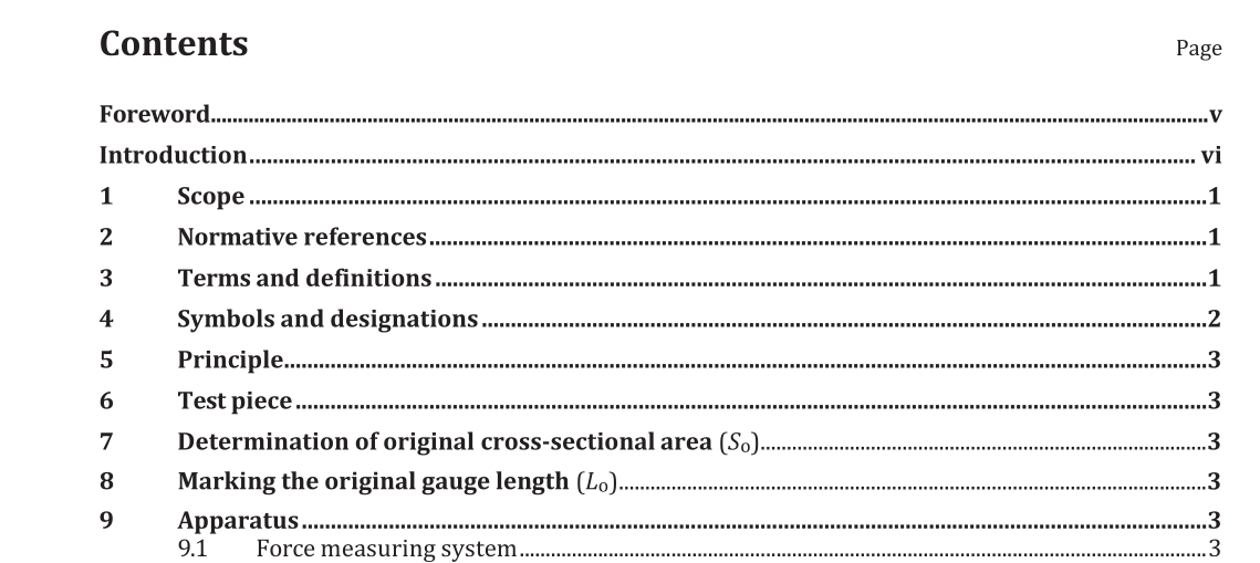
9 Apparatus
9.1 Force measuring system
The force-measuring system of the testing machine shall be calibrated in accordance with ISO 7500-1, class 1 or better.
9.2 Extensometer
For the determination of proof strength (plastic or total extension), the extensometer used shall be in accordance with ISO 9513, class 1 or better, in the relevant range. For other properties (with higher extension), an ISO 9513, class 2 extensometer can be used in the relevant range. The extensometer gauge length shall be not less than 10 mm and shall correspond to the central portion of the parallel length. NOTE When using an extensometer to measure extension up to fracture, the extensometer gauge length, L e , should be approximately equal to the original gauge length, L o , otherwise, the extensometer gauge length, L e , should be at least half as long as the marked original gauge length, L o , but cover no more than 90 % of the parallel length, L c . This will ensure that the extensometer detects all yielding events that occur in the test piece. Further, for measurement of parameters “at” or “after reaching” maximum force, L e will be approximately equal to L o . Any part of the extensometer projecting beyond the cooling device shall be designed or protected from air currents so that fluctuations in the room temperature have only a minimal effect on the readings. It is advisable to maintain reasonable stability of the temperature and air currents surrounding the testing machine.
9.3.2 Permitted deviations of temperature
The cooling device for the test piece shall be such that the test piece can be cooled to the specified temperature, T. The indicated temperatures, T i , are the temperatures measured on the surface of the parallel length of the test piece or measured in the agitated liquid with corrections applied for any known systematic errors, but with no consideration of the uncertainty of the temperature measurement equipment. The permitted deviation between the specified temperature, T, and the indicated temperature, T i , is ±3 °C. The temperature gradient along the surface of the test piece shall not exceed 3 °C. The temperature along the parallel length (L c ) shall be controlled within the permitted tolerances until the final proof strength is reached. NOTE When the final proof strength is reached, temperature control should be attempted but experience has shown that it can be very difficult to control the temperature within the permitted range especially if a gaseous cooling medium is used.
ISO 6892-3:2015 pdf download
