ISO 21806-6:2020 pdf download.Road vehicles — Media Oriented Systems Transport (MOST) — Part 6: Data link layer
1 Scope
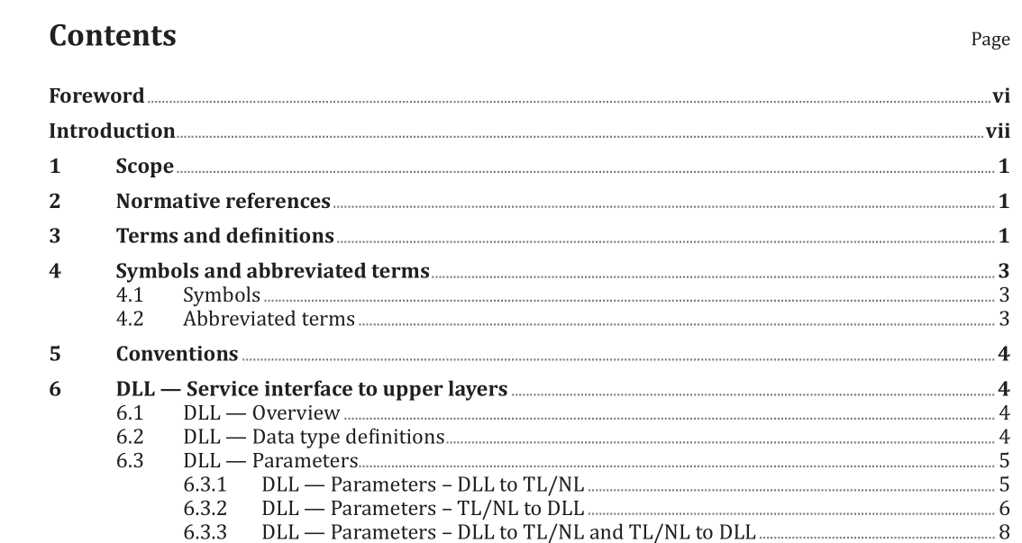
This document specifies technical requirements related to the MOST data link layer functionality. A MOST network is comprised of two or more nodes connected through a physical layer. The data link layer functionality is provided by each node. On each network, all nodes are synchronised and one node provides the system clock. This node is the TimingMaster, while all other nodes are TimingSlaves. The timing configuration of the node (TimingMaster or TimingSlave) determines the tasks that need to be performed on the data link layer.
The data link layer specifies the following subjects:
— the service interface to the network layer;
— the network frame, its areas and indicators;
— the different network channels;
— the different flow control mechanisms;
— the load-adaptive arbitration and the round-robin arbitration;
— the different addressing options;
— the different cyclic redundancy checks, their usage and the CRC acknowledge;
— the frame indicators.
2 Normative references
The following documents are referred to in the text in such a way that some or all of their content constitutes requirements of this document. For dated references, only the edition cited applies. For undated references, the latest edition of the referenced document (including any amendments) applies.
ISO 21806-1, Road vehicles — Media Oriented Systems Transport (MOST) — Part 1: General information and definitions
3 Terms and definitions
For the purposes of this document, the terms and definitions given in ISO 21806-1 and the following apply.
ISO and IEC maintain terminological databases for use in standardization at the following addresses:
— ISO Online browsing platform: available at https:// www .iso .org/ obp
— IEC Electropedia: available at http:// www .electropedia .org/
7.4 DLL — Indicators
Indicators are located in the bit stream of the network frame. They allow the transmission of non-data information in the MOST network bit stream for advanced flow control. Indicators are transmitted on the physical layer in a unique way. Besides the PREAMBLE indicator that designates the first byte of a network frame, the START, END and WAIT indicators are used for, for example identifying start or end of a channel frame (CF) within the network frame. A channel frame is a frame that is transported on a channel within the network frame. The indicators shall be generated as specified in Annex B.
8.1.1 DLL — General
The allocation channel is used to allocate or de-allocate bandwidth in the source data area. Whenever a node intends to make use of network frame bytes in the source data area, it allocates those bytes in an allocation request. An arbitration mechanism allows getting access to bytes that are not yet in use.
ISO 21806-6:2020 pdf download
