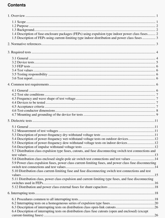
IEEE C37.41:2008 pdf free download.IEEE Standard Design Tests for High-Voltage(>1000 V) Fuses, Fuse and Disconnecting Cutouts, Distribution Enclosed Single-Pole Air Switches, Fuse Disconnecting Switches, and Fuse Links and Accessories Used with These Devices.
To determine the symmetrical short-circuit current, power shall be applied at the p01111 on the voltage wave that minimizes the offset in the first loop (i.e.. power should be applied at an angle approximately equal to the value of the arctan IX’RI with respect to voltage zero, where X/R is the estimated XIR ratio of the test circuit). The symmetrical current may be calculated in accordance with Figure A. 1. The root-mean-square (rms) current should be measured during the first cycle of current.
To determine the X/R of the circuit, an asymmetrical prospective current is required. X/R can then be obtained from the ratio of the peak asymmetrical current (of a fully asymmetrical current) to the rms syinmcthcal current, using Figure C. 1. or by appropriate equivalent digital analysis.
6.1 .2.2.2 X/Rand test current for long-duration tests
rhere the interrupting tests involve long melting times (i.e.. greater than 1.5 cycles), it may be appropriate to use alternate methods to dctcrminc the circuit X/R ratio and tcst current.
For these tests, the test current may be taken as the prospective current (measured per 6.1.2.2.1) if the melting time is still quite short or the rms value of the current measured immediately prior to the initiation of arcing. The reason for measuring the actual circuit current during the test rather than the prospective current (i.e.. with the test device replaced by a link of negligible impedance is that heating of circuit components or other factors may result in a lower actual current at device melting than the current measured during a practical-duration bolted fault current test.
It should be noted that when the alternate test method for test series 3 tests on current-limiting fuses is used (6.6.2), the “melting time” for determining the XIR and test current is from the time when the high-voltage current starts to flow to the time when the fuse melts. If the fuse begins to arc immediately (i.e.. the elements have melted beibre changeover occurs), then the current shall be taken as the prospective current (see 61.2.2.1).
6.1.2.3 ApplicatIon of test power
The device shall he tested in the circuit described in 6.1.2.1 and 6.1.2.2. with the negligible impedance connection removed. Power shall be applied at a point on the voltage wave that produces the conditions specified in the appropriate table covering the particular device being tested.
6.1.2.4 Recovery voltage
After current interruption, the power-frequency recovery voltage shall be maintained across an open device for the duration specified in Table 6, Table 7. Table 8. Table Ii. Table 14. Table 17. and Table 19. Where test station limitations make it difficult for the full value of recovery voltage to he maintained for specified durations longer than 10 s. the test circuit may be switched to an auxiliary source. Such changeover shall not be made until a time of at least 10 s has elapsed from current interruption Any necessary circuit
IEEE C37.41:2008 pdf free download
