AS 2005.21.2:1990 pdf – Low voltage fuses—Fuses withenclosed fuse-links Part 21.2:Supplementary requirements for fuses for useby authorized persons (fusesmainly for industrial application)—Standardized fuse systems-Fuses with fuse-links for bolted connections.
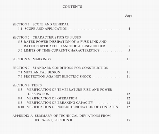
8.3 VERIFICATION OF TEMPERATURE RISE AND POWER DISSIPATION.
8.3.1 Arrangement of the fuse. The test arrangement for fuse-links shall be as shown in Figure 4 and mounted vertically.
8.3.3 Measurement of the power dissipation of the fuse-link. The points of measurement of power loss are shown in Figure 4.
8.4 VERIFICATION OF OPERATION.
8.4.1 Arrangement of the fuse. The test arrangement of the fuse-link shall be as shown in Figure 4 and
mounted vertically.
8.5 VERIFICATiON OF BREAKING CAPACITY.
8.5.1 Arrangement of the fuse. The test arrangement of the fuse-link shall be as shown in Figure 5.
8.5.8 Acceptability of test results. The requirements of AS 2005.10 apply and in addition fuse-links shall
operate without the melting of the fine fuse wire and without mechanical damage to the test rig.
8.10 VERIFICATION OF NON-DETERIORATION OF CONTACTS.
8.10.1 Arrangement of the fuse. The fuse shall be arranged for test in accordance with Clause 8.3.1 of AS 2005.10 using a fuse-link which, at the rated current of the fuse-holder, attains a power dissipation equivalent to the rated power acceptance of the fuse-holder.
The temperature rise of the fuse-holder contacts shall be determined by means of measuring devices that appear most suitable, provided that the measuring devices cannot appreciably influence the temperature of the contacts.
8.10.2 Test method. The temperature rise values of the fuse-holder contacts shall be measured in accordance with Clause 8.3.4.1 of AS 2005.10 before and after the following test cycles:
(a) Each test cycle shall be as follows:
Load period 25% of the conventional time (see Table 5.1 of No-load period 10% of the conventional time AS 2005.10)
Test current non-fusing current (l)
During the no-load period the fuse shall be cooled down to a temperature below 35°C, if necessary using additional cooling means, e.g. an air vent.
(b) The test shall continue for 250 cycles, and if necessary, for a further 500 cycles (see Clause 8.10.3).
8.10.3 Acceptability of test results. If after 250 cycles, the measured temperature rise values of the contacts do not exceed the temperature rise values measured at the beginning of the test by more than 15°C the fuse-holder is considered to have passed this test.
If after 250 cycles the temperature risc values of the contacts exceed the values measured at the beginning of the test by more than 15°C, the test may be continued for a further 500 cycles, after which the fuse-holder is considered to have passed this test provided the temperature rise values of the contacts do not exceed the temperature rise values measured at the beginning of the test by more than 20°C.
AS 2005.21.2:1990 pdf – Low voltage fuses—Fuses withenclosed fuse-links Part 21.2:Supplementary requirements for fuses for useby authorized persons (fusesmainly for industrial application)—Standardized fuse systems-Fuses with fuse-links for bolted connections
