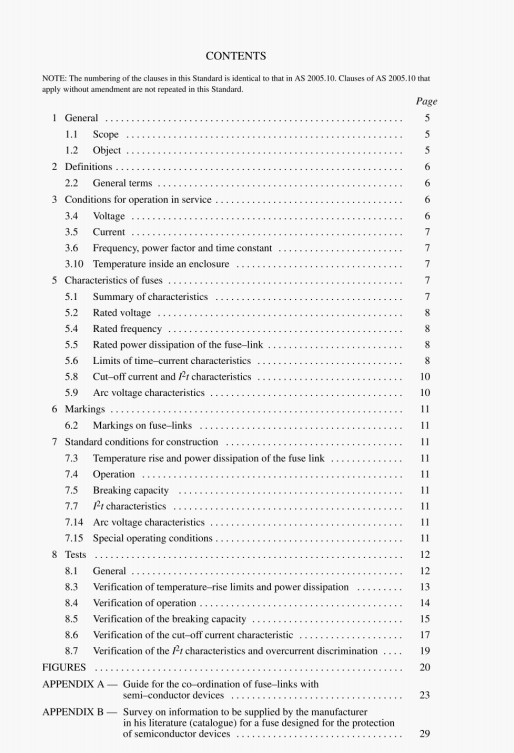
AS 2005.40:1989 pdf – Low voltage fuses-Fuses withenclosed fuse-links Part 40:Supplementary requirements for fuse-links for the protection of semiconductor devices.
8.3.3 and 8.3.4.2 Measurement of power dissipation of the fuse-link
In addition to Sub-clause 8.3.3 of IEC Publication 269-1, the following applies: The power dissipation test shall be made successively at least at 50% and at 100% of rated current at rated frequency.
8.3.5 Acceptability of test results
The temperature rise and the power dissipation of the fuse-link shall not exceed the values specified by the manufacturer.
After the tests, the fuse-link shall not have significantly changed its characteristics.
8.4 Verification of operation
8.4. 1 Arrangement of fuse-link
The arrangement of the fuse-link for the verification of operation shall he as described in Sub-clauses 8. 1 .4 and 8.3.1.
8.4.3.2 Verification of rated current
The fuse-link is tested under the same test conditions as indicated in Sub-clause 8.3.1.
It is subjected to 100 test cycles, each consisting of an “on” period of 0. I times the conventional time as specified in Table 11 of IEC Publication 269-1 at rated current and an “oil’ period of the same duration.
After this test, the fuse-link shall not have changed its characteristics (see Sub-clause 8.3 5).
The time-current characteristics may he verified on (lie basis of the results obtained from the oscillographic records taken during the performance of the tests according to Sub-clause 8.5.
The following periods are determined:
from the instant of closing the circuit until the instant when the voltage measurement shows the beginning of the arc;
from the instant of closing the circuit until the instant when the circuit is definitely broken.
The values of pre-arcing and operating times SO determined, referred to the abscissa corresponding to the value of prospective current, shall he within the time-current zone indicated by the manufacturer.
For ac. prospective currents leading to actual pre-arcing time values of less than ten cycles of rated frequency and up to current values where the melting is adiabatic, the currents shall he initiated in such a manner that the prospective current will be symmetrical.
For d.c., the time-current characteristics determined for a.c. are applicable for times longer than 15t for the relevant circuit.
When, for the fuse-links of a homogeneous series (see Sub-clause 8.1.5.2), the complete test according to Sub-clause 8.5 is made only on the fuse-link having the largest rated current, it shall be sufficient to verify only the pre-arcing time for the fuse-link having the smallest rated current.
Pre-arcing time-current characteristics can he determined at any convenient voltage value and on any linear circuit. Tests to determine operating time-current characteristics require the proper voltage values and circuit characteristics.
AS 2005.40:1989 pdf – Low voltage fuses-Fuses withenclosed fuse-links Part 40:Supplementary requirements for fuse-links for the protection of semiconductor devices
