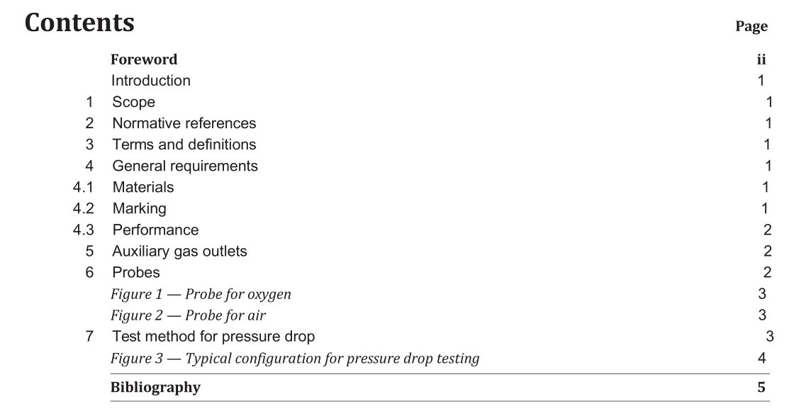
BS 4272-4:2018 pdf download.Anaesthetic and analgesic machines Part 4: Specification for auxiliary gas outlets and probes
1 Scope
This British Standard specifies the dimensions and requirements for air and oxygen auxiliary gas outlets and probes used on anaesthetic and analgesic machines. These outlets are intended to provide a source of medical gas at pressures between 375 kPa and 420 kPa for devices such as ventilators and jet injectors used in bronchoscopy and laryngoscopy.
2 Normative references
The following documents, in whole or in part, are normatively referenced in this document and are indispensable for its application. For dated references, only the edition cited applies. For undated references, the latest edition of the referenced document (including any amendments) applies.
BS EN ISO 4135, Anaesthetic and respiratory equipment — Vocabulary
BS EN ISO 6506‑1, Metallic materials — Brinell hardness test — Part 1: Test method
BS EN ISO 15001, Anaesthetic and respiratory equipment — Compatibility with oxygen
3 Terms and definitions
For the purposes of this document, the terms and definitions given in BS EN ISO 4135 apply.
4 General requirements
4.1 Materials
4.1.1 The connecting surfaces of auxiliary gas outlets and probes shall be manufactured from material with a minimum hardness value of 120 HBW 2.5/62.5 in accordance with BS EN ISO 6506‑1.
NOTE 1 The mechanical properties of the probes are specified to minimize the risk of cross-connection in conditions of normal use and reasonably foreseeable misuse.
NOTE 2 Hardness equivalence tables are provided in BS EN ISO 6506-4.
NOTE 3 Stainless steel is considered a suitable hardwearing material.
4.1.2 Auxiliary gas outlets and probes shall be manufactured from oxygen‑compatible materials in accordance with BS EN ISO 15001.
4.2 Marking
Auxiliary gas outlets and probes shall be durably and legibly marked with “AIR” or “OXYGEN” or an equivalent symbol, as appropriate.
Auxiliary gas outlets shall be durably and legibly marked with the nominal outlet pressure in units of kPa.
NOTE Equipment incorporating auxiliary gas outlets or probes may be subject to requirements concerning colour, legibility and durability.
4.3 Performance
4.3.1 Gas shall not flow until the probe is fully connected and locked into the auxiliary gas outlet.
4.3.2 A tactile and/or audible indication of locking shall be perceived on retention of the gas‑specific probe.
NOTE Some leakage of gas is inevitable when connecting the probe to the outlet and is considered not to constitute flow.
4.3.3 When the probe is connected to the auxiliary gas outlet the probe shall not detach from the outlet when subjected to an internal pressure of 1000 kPa.
4.3.4 When the probe is connected to the auxiliary gas outlet the leakage to atmosphere shall be not greater than 0.2 ml/min when subjected to an internal pressure of 420 kPa.
4.3.5 When tested in accordance with Clause 7, the pressure drop across the assembled auxiliary outlet and probe shall be not greater than 5 kPa when subjected to an inlet pressure of (375 ±10) kPa at a flow rate of (30 ±5) l/min.
BS 4272-4:2018 pdf download
