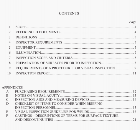
AS 3978:2003 pdf – Non-destructive testing- Visual inspection of metal products and components.
5.2.4 Factors a/jc!ing the choice of magnifier
Hand-held, single or multi-element magnifiers having a magnification of x2 to x4 are adequate for a wide range of industrial applications. The benefits of easy manipulation and relatively strain-free binocular vision can offset the reputed advantages of higher magnification, which may be illusory for the following reasons:
(a) Higher magnification involves a shorter eye-to-lens distance and a shorter working distance.
(b) Short working distances, where only one eye can be used, are a contributory cause of operator fatigue.
(c) The field of view is much reduced and hence the time of inspection increased.
(d) The depth of focus is much smaller and spatial relationships between different portions of the surface under inspection become difficult to assess.
5.3 Surface feature modelling equipment and materials
Surface profiling devices and cold setting resins or modelling clay may be used to obtain a permanent record of surface features for direct measurement or comparison.
5.4 Remote viewing equipment
Television, e.g. CCD cameras, fibre-optic devices and borescopes, may be used. Such equipment shall have sufficient resolution and contrast to resolve discontinuities present in a reference Standard.
5.5 Photographic equipment
Photographic and recording equipment shall be capable of resolving and capturing specific
features of discontinuities.
6 ILLUMINATION
6.1 General
Visual inspection shall be carried out under suitable lighting conditions. The optimum level of illumination for inspection at low magnification is dependent on several factors, including the following:
(a) The location of the work-piece and the ease of access to the surface to be examined.
(b) The nature and reflectivity of the surface.
(c) The direction of illumination, i.e. direct or oblique.
(d) The degree of light gathering or light loss in the optical system employed.
Recommendations on illumination levels for various visual inspection tasks are given in AS 1680. A minimum illuminance of 400 lx shall be employed.
6.2 Location of the work-piece
The ideal viewing condition occurs when the surface under examination is tilted to enable it to be examined from more than one angle and under more than one intensity of illumination. If the work-piece is immovable, viewing shall be carried out using a variety of positions for both the eye and the light source.
7 INSPECTION SCOPE AND CRITERIA
7.1 General requirements
Unless otherwise specified in the engineering drawing, specification/code or purchaser’ s
requirements, visual inspection shall cover I 00% of the surface requiring inspection. Where
complete inspection is not possible, the inspector shall document fully, with clear
measurements, the areas not inspected.
7.2 The terminology, identification and evaluation of discontinuities
The terminology used shall be in accordance with the referenced documents, definitions, or
terms described in the relevant product codes. If there is any doubt about the identification
of a particular discontinuity, it is recommended that colour photographs of appropriate
resolution be taken for inclusion in the inspection report.
NOTE: Other non-destructive testing methods may be used to assist in the evaluation of surface
discontinuities.
AS 3978:2003 pdf – Non-destructive testing- Visual inspection of metal products and components
