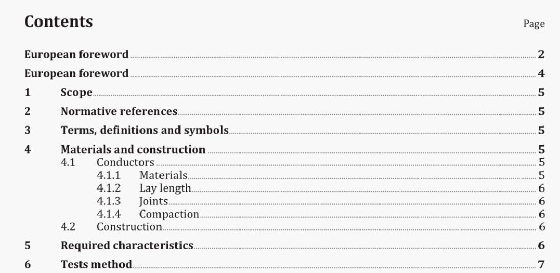
BS EN 2234:2018 pdf download.Aerospace series – Cable, electrical, fire resistant- Technical specification
1 Scope
This document specifies the required characteristics and test procedures for fire resistant or fire-proof electrical cables for use in aircraft electrical systems. These cables should also maintain a specific surface resistance when they are subjected to a flame of 1 100 °C after 5 minutes (fire resistant) or 15 minutes (fire-proof) exposure. The insulation of these cables is designed to withstand aircraft voltages at a frequency not exceeding 2000 Hz. Unless specified by individual product standards the maximum demonstrated ac voltage of rating of these cables is 115 V rms (phase to neutral) and 200 V rms (phase to phase) and a long term temperature of up to 260。C (ambient temperature plus temperature rise in conductor).
4.1.2 Lay length
Up to 9 mm2 cross section inclusive [code 090), concentric or unilay conductors are used. The lay for the stranded conductor, checked over the outside layer of a test piece 1 m long, shall be between 8 times and 16 times the maximum diameter of this conductor. For sectional areas between 14 mm2 and 68 mm2 [codes 140 to 680], the conductor comprises concentric or bunched conductors twisted together. The lay of the strands for the basic concentric or bunched conductors shall not exceed 30 times the diameter of the concentric or bunched conductor in question. The lay for concentric [or bunched) conductors, measured over the outer layer of the conductor, shall be between 8 times and 16 times the maximum conductor diameter. In all cases the lay of the outer layer shall be left-hand.
4.2 Construction Finished cables
The insulation shall be of a material, which takes on the circular shape of the conductor throughout its length. It shall closely cover the conductor without adhering to it, so that it reduces the corona effect and the risk of blistering and heat corrosion due to voids and gaseous discharges. The insulation shall be neither too tight nor too loose, so as to provide satisfactory mechanical characteristics and be easily removable using commercially available tools. (See Table 1, S 6.45). The protective sheath shall be of a material, which takes on the round shape of the insulated conductor lying under it. It shall provide adequate protection from mechanical damage and contamination by liquids, as specified in the product standard. The outer surface shall be smooth and suitable for identification marking. The protective sheath shall not have a corrosive effect on the screen and shall be resistant to fungus and other.
BS EN 2234:2018 pdf download
