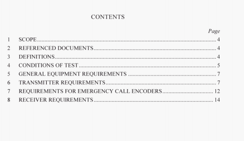
AS/NZS 4770:2000 pdf – MF and HF radiocommunicationsequipment in the land mobile serviceutilizing single sideb and suppressed carrier emission.
The frequency is measured with the transmitter connected to an artificial antenna. The transmitter shall he modulated with a signal of 1000 Hz. The 1000 Fl, signal shall he subtracted from the measured frequency to calculate the transmitter frequency. The test shall be carried out at the highest test frequency of the intended frequency of operation. if it is demonstrated that the frequency is determined from a single reference source. If this cannot be demonstrated, the test shall be carried out on all test frequencies. An alternative method is the direct measurement of the carrier frequency if available.
Measurements shall be made under normal test conditions and repeated under extreme test conditions.
6.2 Output power and intermodulation products
6.2.1 Limit
The peak envelope power of the transmitter shall not deviate from the manufacturer’s declared output power by more than ±1.5dB under normal test conditions and ±3dB under extreme test conditions. The manufacturer’s declared output power shall not exceed 100 W.
NOTE: The appropriate authority may approve the use of higher power to meet situations of a special nature.
The value of intermodulation products shall not exceed 25 dB below the higher of the two levels, measured under normal conditions.
The transmitter is connected to the artificial antenna. The tests are carried out in accordance with the duty cycle specified in Clause 4,8.
A soltage-calibrated oscilloscope, spectrum analyser and mean power meter as shown in Figure 1 are coupled to the output of the transmitter to display the transmitter output voltage and envelope waveform.
The transmitter is modulated by two audio frequency wncs applied simultaneously. The tones shall be 700 and 2300 Hz and at a level 10dB above that required to drive the transmitter to the ALC threshold point. The two-tone input is adjusted to maintain equal two-tone levels at the transmitter output. The peak envelope voltage is measured and recorded as V,.
[he 2300 Hz tone is removed leaving the transmitter modulated only by the 700 Hz tone. The output power of this signal tone is measured with a mean power meter and recorded as (Ps) and the peak envelope voltage recorded as V2.
For the purpose of this Standard, the peak envelope power is then calculated using the following equation:
Following a step increase of 20 dB in the level of the modulating signal, the time takenshall not exceed 3 ms for the output power of the transmitter to-
(a)be reduced by 63% of the difference between the transient peak and the final steady
state value;or
(b)reach a level not more than 0.5 dB above the final steady state value;whichever is the greater.
AS/NZS 4770:2000 pdf – MF and HF radiocommunicationsequipment in the land mobile serviceutilizing single sideb and suppressed carrier emission
